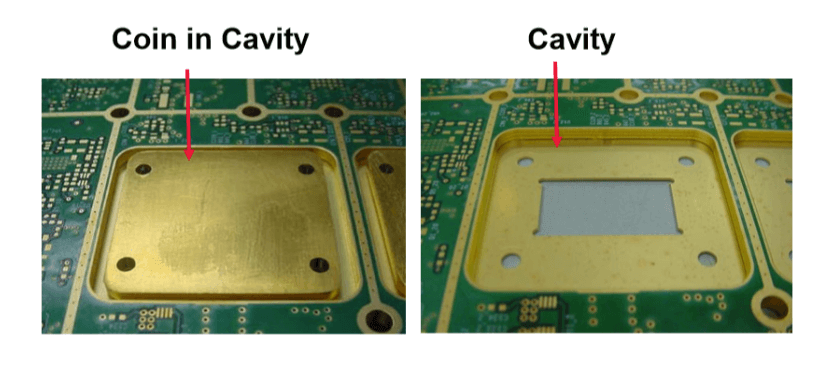

The key to a successful paste print is optimizing the critical print parameters 1.) Solder pad to cavity wall air gap, 2.) Squeegee flap length and thickness, 3.) Print fixture support, and 4.) Pocket stencil alignment. Single pass, multi-level solder paste printing is the most challenging aspect to implementing cavity technology into a high volume manufacturing environment. SMT testing of the cavity boards assembled with the 0.4mm pitch BGA packages at multiple cavity depths has demonstrated that PCBs can be successfully paste printed, assembled, and reflowed in the same multi-level processes with the existing equipment capability. The use of cavities in a PCB as a method to reduce the component height or to increase component clearances is a viable technology.

The cavity design and assembly issues identified during the design of experiments (DOEs), the findings, reliability results, and conclusions will be discussed in this paper. The methodology to create the cavity in the PCB has evolved over time as technologies have advanced and the manufacturing process varies by the individual PCB fabricator as well as the reasons for using the cavity technology.įor the purpose of this paper, a cavity will be defined as a hole in the PCB going from the outer copper layer to an inner copper layer, but not completely through the PCB. RothĬavity technology in a Printed Circuit Board (PCB) has existed for many years.


 0 kommentar(er)
